Electronics
- #Soudure
- #Proteus
- #KiCad
- #Logisim
- #VHDL
My passion having led me to study electrical engineering, I have carried out many projects, from the simple adapter to the console controller, including the famous line-following robot.
-
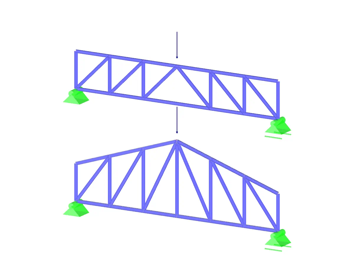
Bicycle monitor
During a project in connection with the school we had the possibility to choose our project. As we were cycling, my teammate and I chose to make a bicycle monitor that could calculate speed, distance travelled and manage session times. To this we added a jacket with a flashing light to ensure better safety.
EnlargeBicycle monitor
-
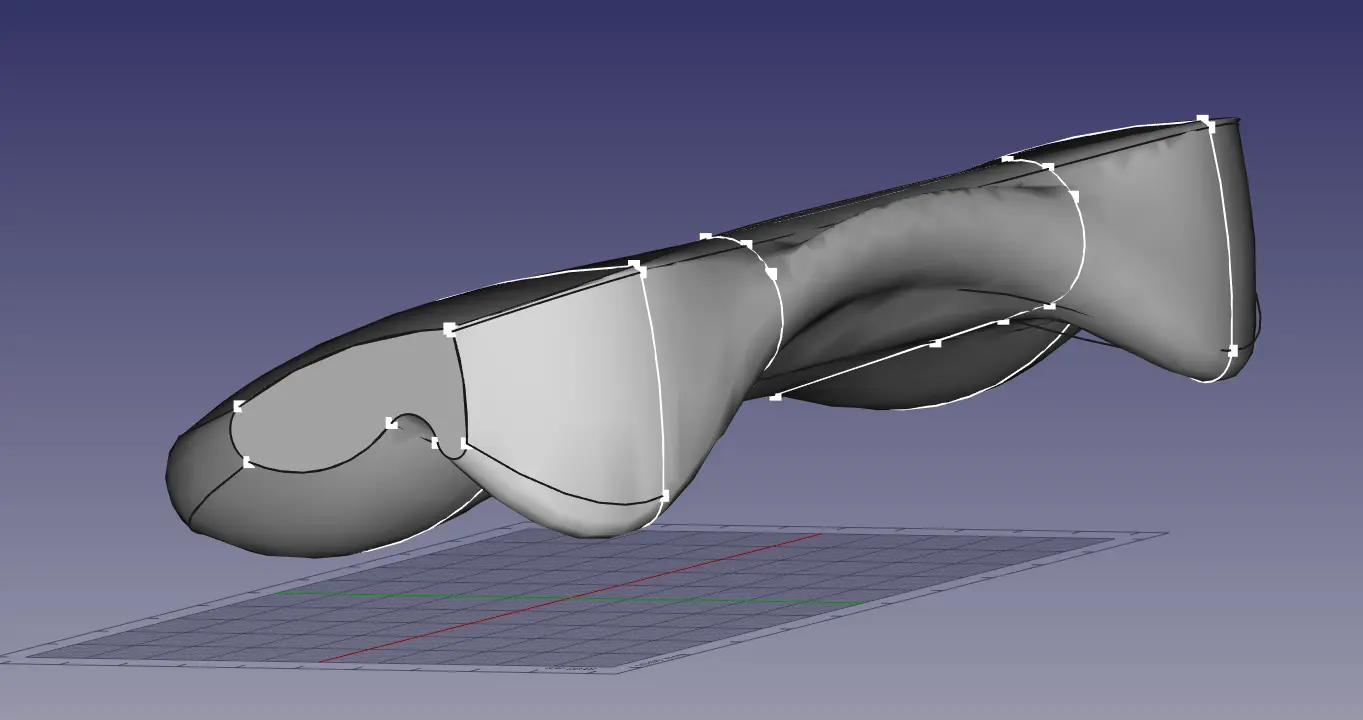
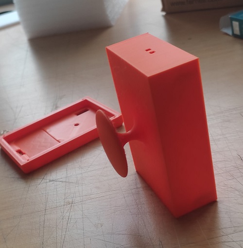
The objective of this project was to produce a system capable of effectively describing the activities of a cyclist. Although we initially opted for a prototype version on a board, we decided during the course of the project to produce an alpha capable of being used on a session. The problems of compactness and miniaturisation came up very quickly and I opted for SMD components, this being the first project where I used them. The choice of the placement of the main components on the board was also constrained by the desired sports ergonomics here.
-
The board was made on Proteus, the electronic CAD software used by my school, and is 120*50 mm with 33 components and 73 tracks. Once all the functionalities had been tested on a test board, I made the PCB in physics. However, the board had some manufacturing imperfections and was unusable, and due to lack of time I could not make a second one. I was however able to check the mechanical compatibility, and invite you to discover the mechanical part of this project that I also realized on github where you will find all the source files.
ShrinkThe objective of this project was to produce a system capable of effectively describing the activities of a cyclist. Although we initially opted for a prototype version on a board, we decided during the course of the project to produce an alpha capable of being used on a session.
The problems of compactness and miniaturisation came up very quickly and I opted for SMD components, this being the first project where I used them. The choice of the placement of the main components on the board was also constrained by the desired sports ergonomics here.
The board was made on Proteus, the electronic CAD software used by my school, and is 120*50 mm with 33 components and 73 tracks.Once all the functionalities were tested on a test board, I made the PCB in physics. However, the board had some manufacturing imperfections and remained unusable, and due to lack of time it was impossible for me to make a second one. I was however able to check the mechanical compatibility, and invite you to discover the mechanical part of this project that I also realized as well as its github where you will find all the source files.
-
-
From transistor to CPU
Always trying to understand how everything around me works, I came across processors and the question "how does it work? And what better way to answer it than to build one! I then opened Logisim Evolution, a logic simulation software, and still today I am working on my own RISC-V microprocessor.
EnlargeFrom transistor to CPU
-
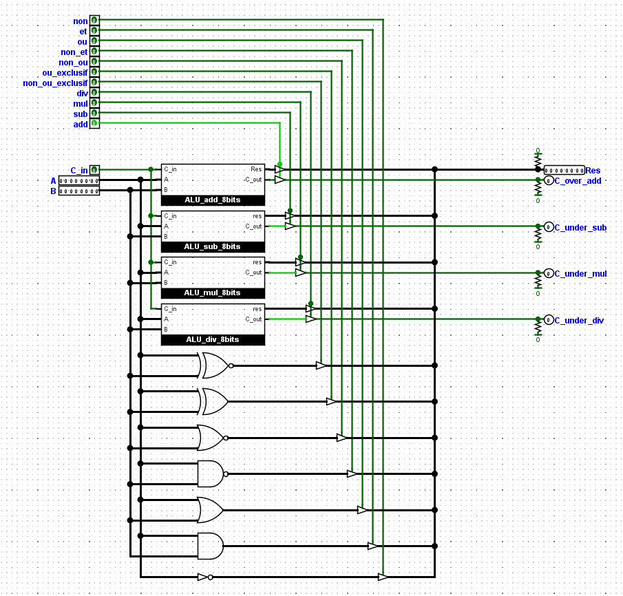
The aim of this project is above all to understand the functioning and the steps of creation of a (micro) processor. So I decided to build one starting from transistors and going up to the etched chip. To do this, I use logisim-évolution, a logic simulation software capable of running small microprocessors visually and converting them into VHDL to put them on FPGA systems. I also work on Xilinx boards in VHDL. I have already made a 32-bit ALU, starting from transistors, capable of following 11 custom instructions like addition, multiplication, or binary comparisons.
-
The objective is to realize a 32-bit microprocessor, respecting the RISC-V instruction set. As a first step, the three stages of a SAP, the simplest processors to build, will be implemented. If you want to learn more about this project, please visit github where you will find all the source files.
ShrinkThe aim of this project is above all to understand the functioning and the steps of creation of a (micro) processor. So I decided to build one starting from transistors and going up to the etched chip.
To do this, I use logisim-évolution, a logic simulation software capable of running small microprocessors visually and converting them into VHDL to put them on FPGA systems. I also work on Xilinx boards in VHDL. I have already made a 32-bit ALU, starting from transistors, capable of following 11 custom instructions like addition, multiplication, or binary comparisons. The objective is to realize a 32-bit microprocessor, respecting the RISC-V instruction set. As a first step, the three stages of a SAP, the simplest processors to build, will be implemented. If you want to learn more about this project, please visit github where you will find all the source files.
-
-
Controller
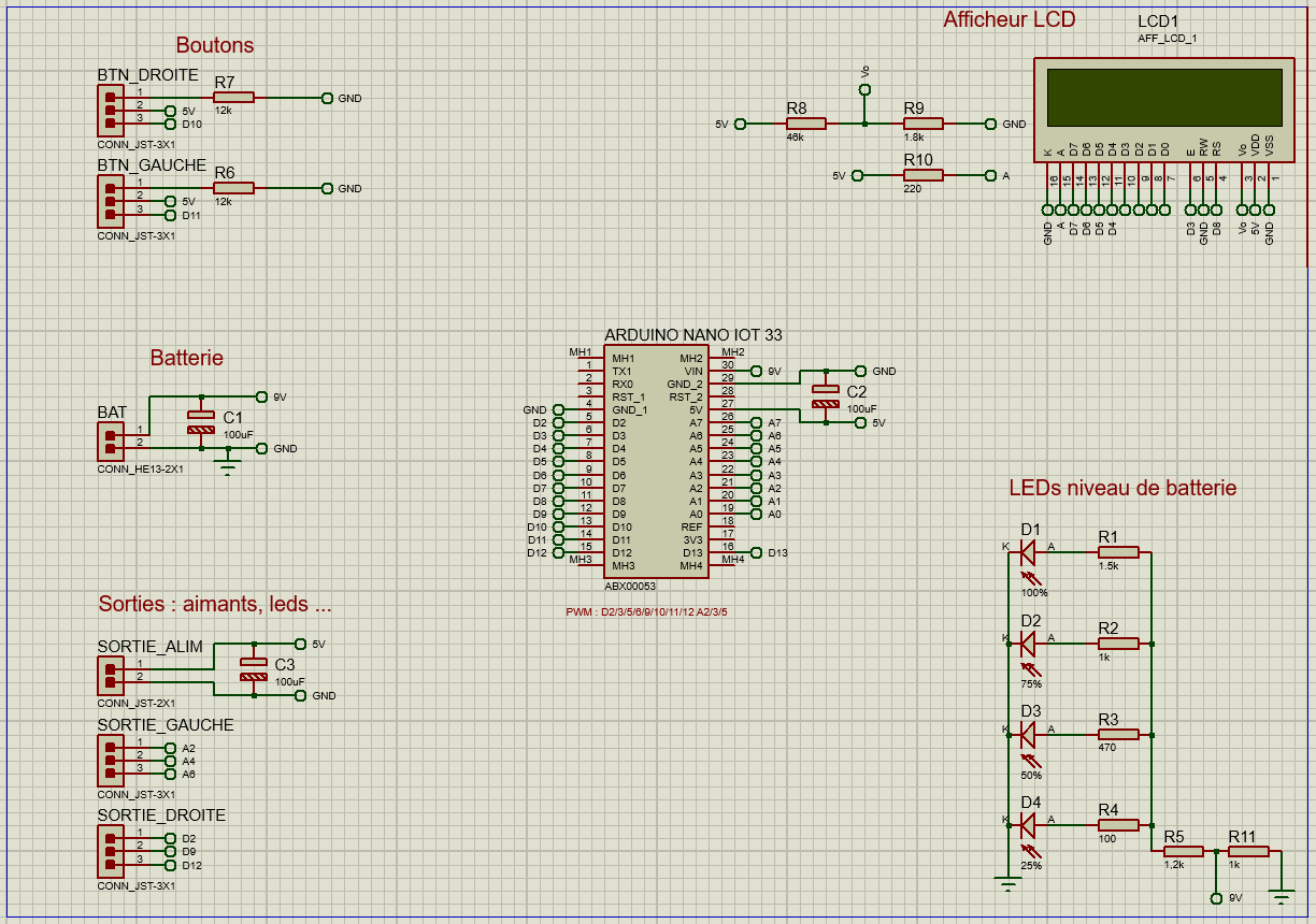
The video game controller is one of the most common controllers, but its integration in DIY or Arduino projects can be laborious for simple prototyping stages. So I decided to make my own controller with the goal of making it easily accessible on Arduino.
EnlargeController
-
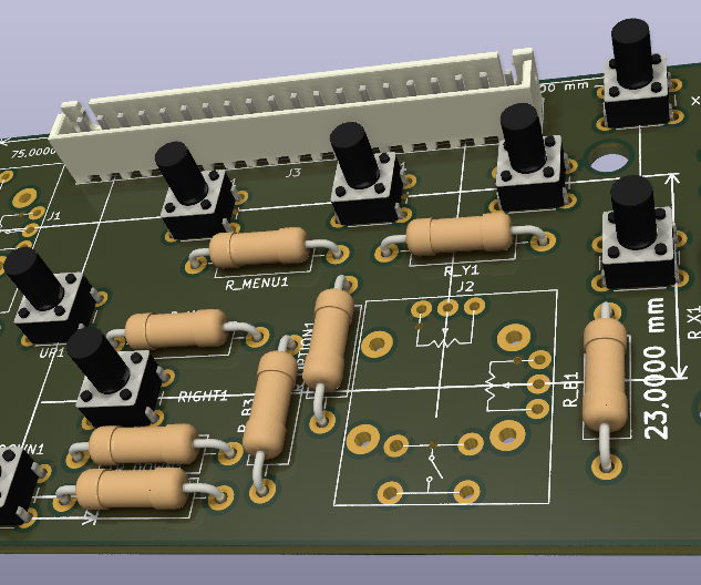
Being able to control and receive information during a robotics project is essential, but the implementation is often time-consuming and poorly done. I therefore decided to create a controller capable of responding to this problem simply and efficiently. In order to make it easier for everyone to implement, I have forced myself to use only feed-through components. In order to facilitate the implementation in any project, each element has its own signal that can be processed independently from the others.
-
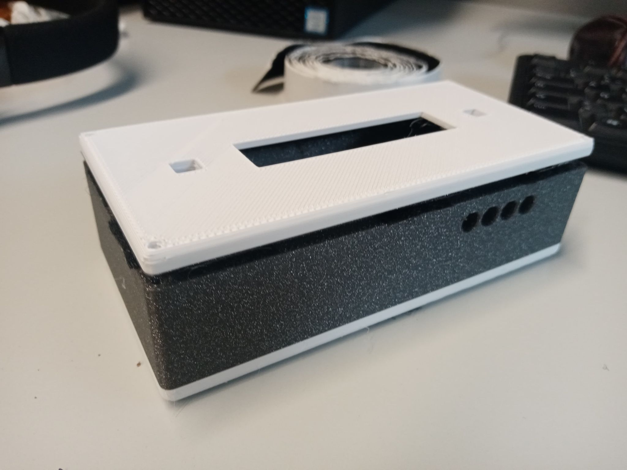
The board is currently 100*53 mm (rounded edges) with nearly thirty components. However, it is likely to evolve further as it needs to be fitted with a port extension system to reduce its impact on the number of pins on the Arduino, as well as a screen to display more information. Like all my projects, you can find it in free access on github with more explanations on how the project will work.
ShrinkBeing able to control and receive information during a robotics project is essential, but the implementation is often time-consuming and poorly done. I therefore decided to create a controller capable of responding to this problem simply and efficiently.
In order to make it easier for everyone to implement, I have forced myself to use only feed-through components. In order to facilitate the implementation in any project, each element has its own signal that can be processed independently from the others. The board is currently 100*53 mm (rounded edges) with nearly thirty components. However, it is likely to evolve further as it needs to be fitted with a port extension system to reduce its impact on the number of pins on the Arduino, as well as a screen to display more information. Like all my projects, you can find it in free access on github with more explanations on how the project will work.
-